


Bringing affordable power to the Canadian North
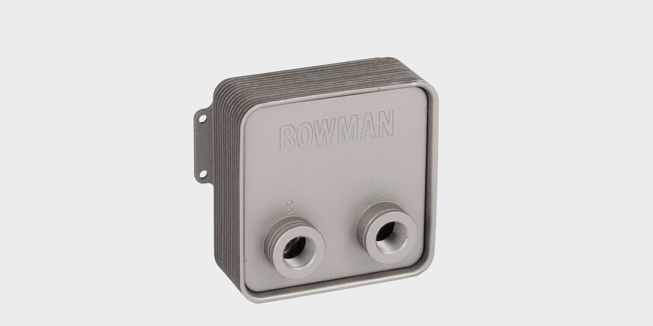
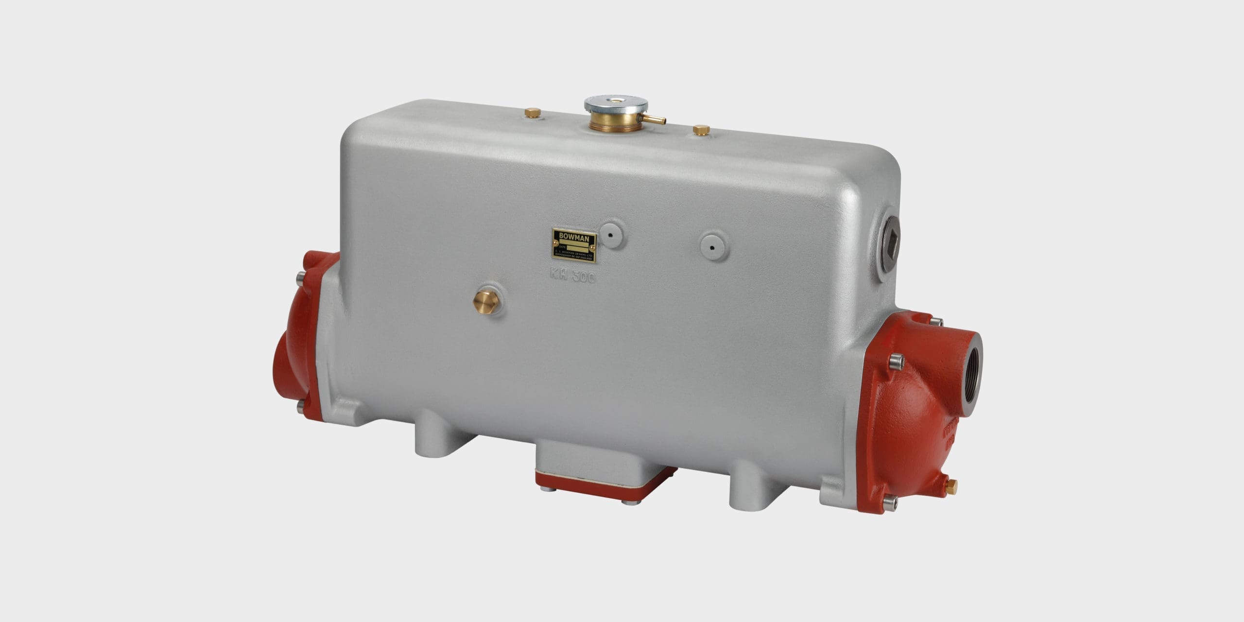
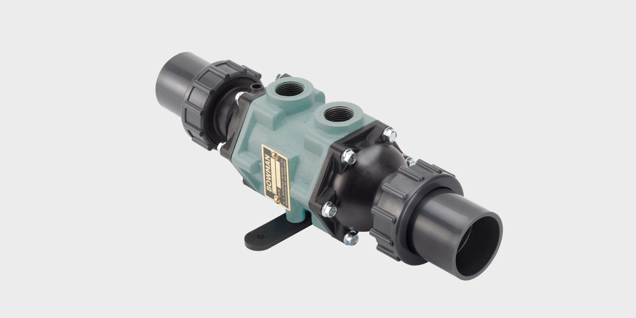
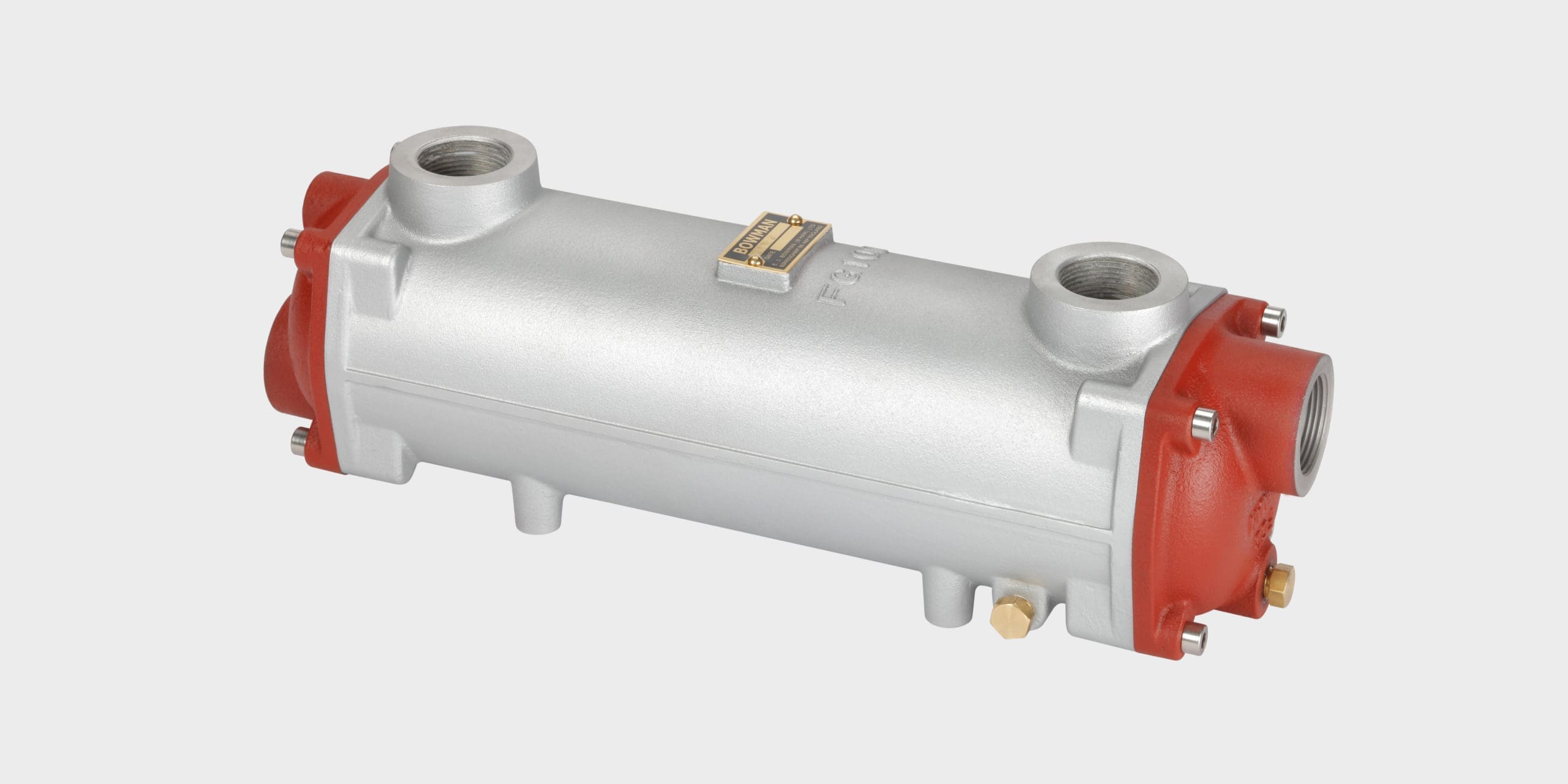
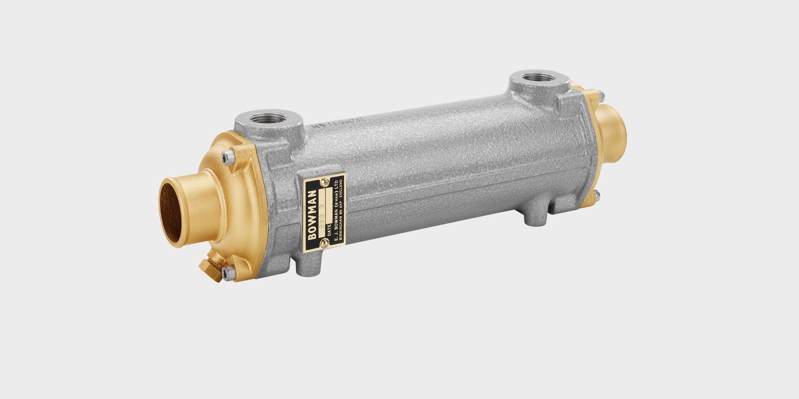
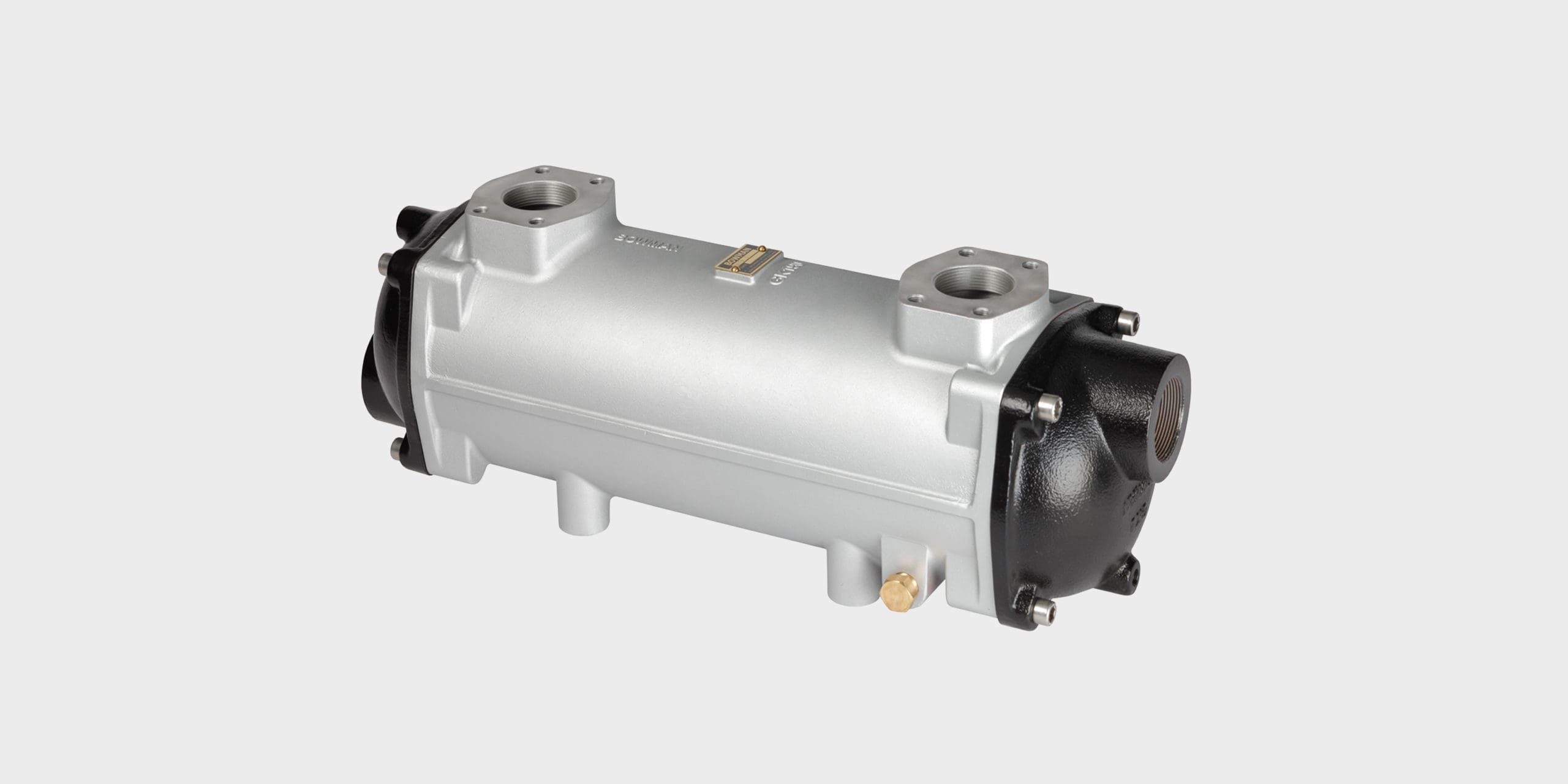
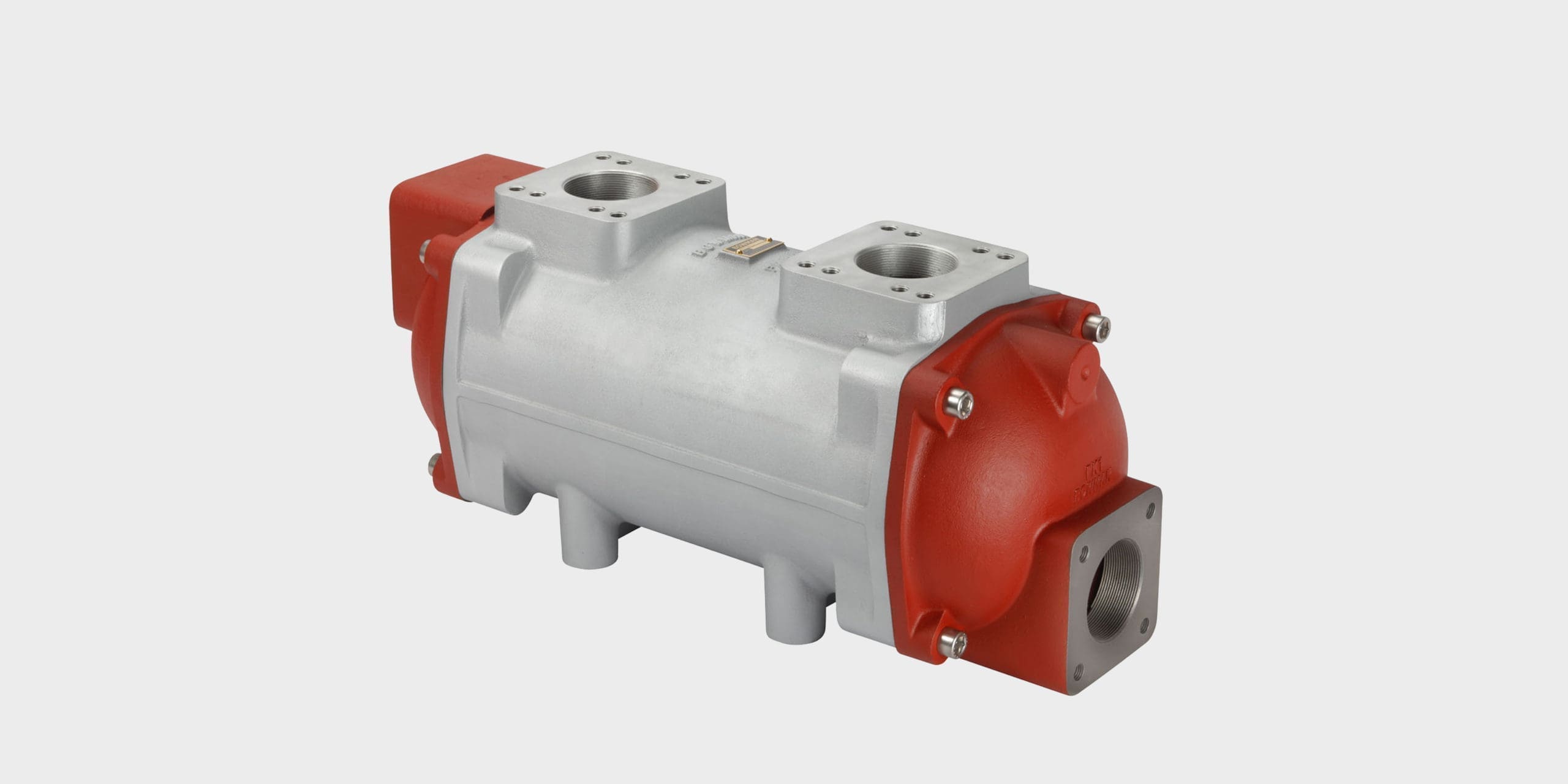
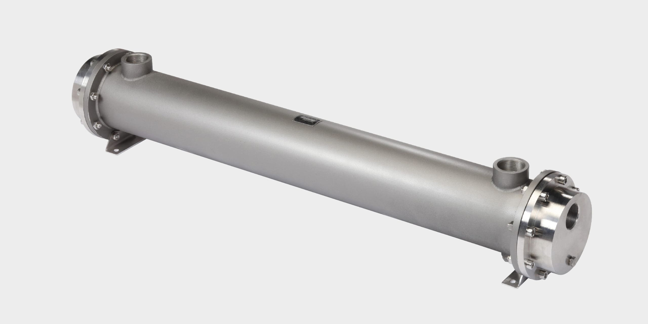
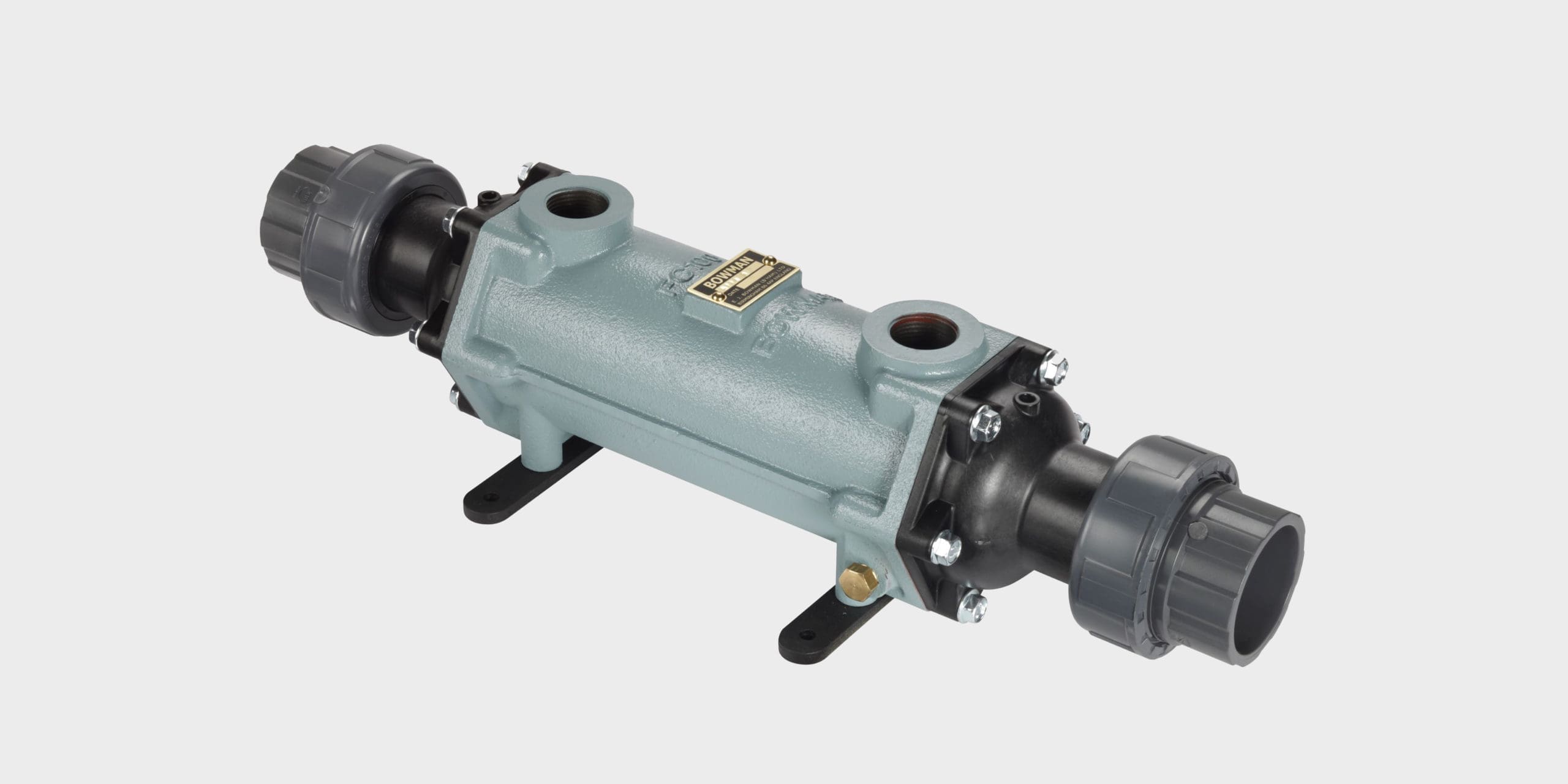
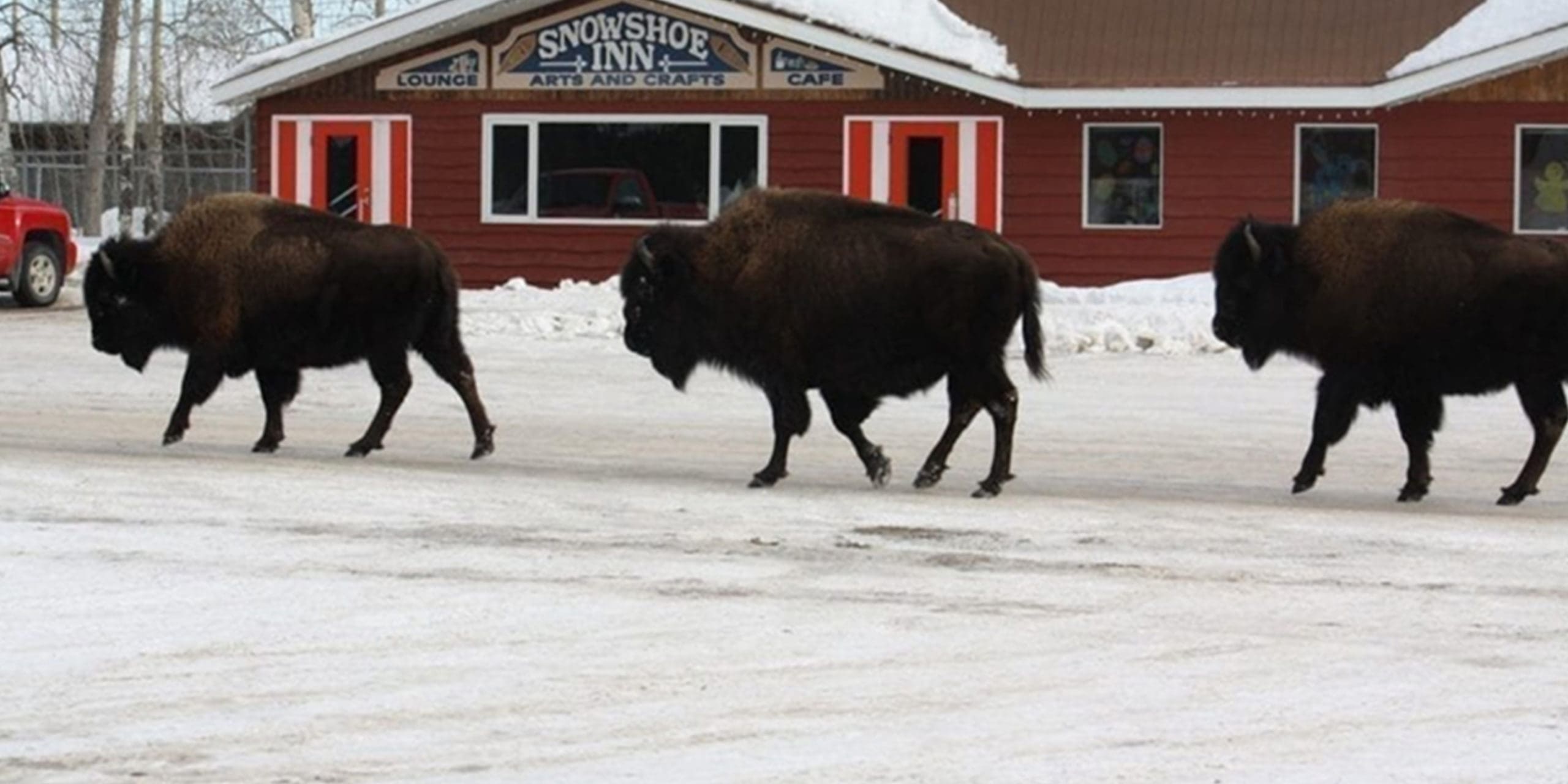
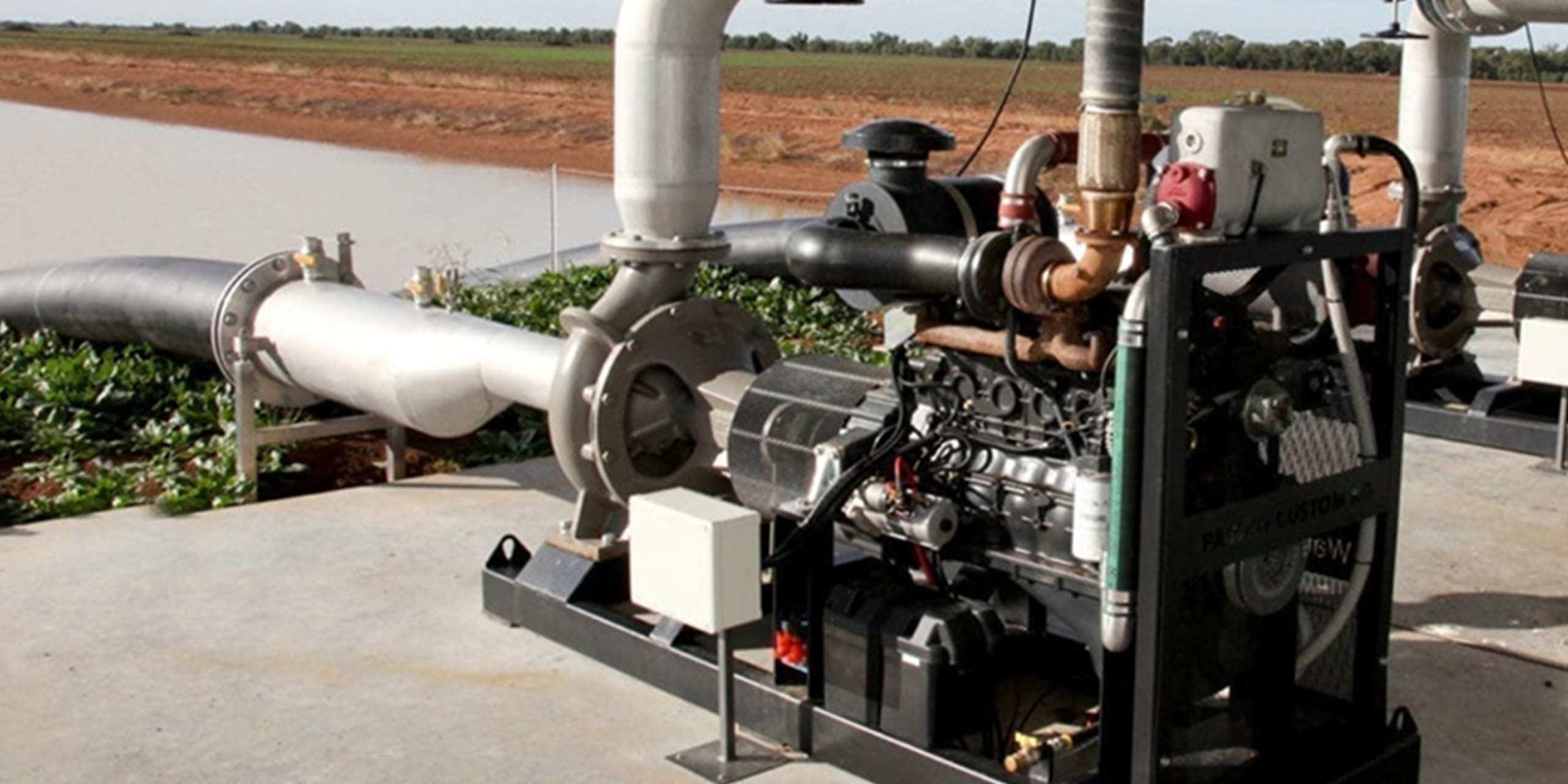
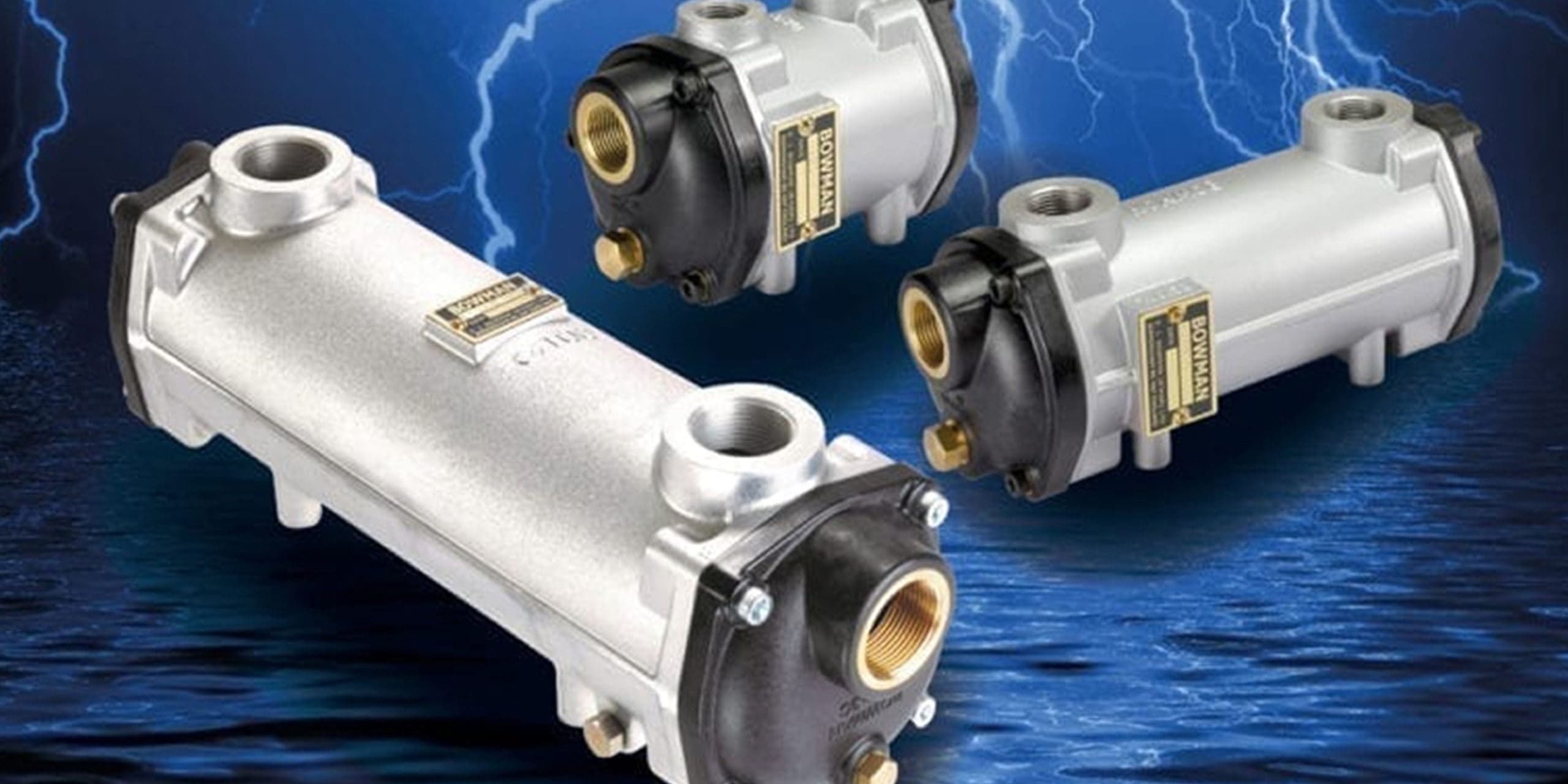
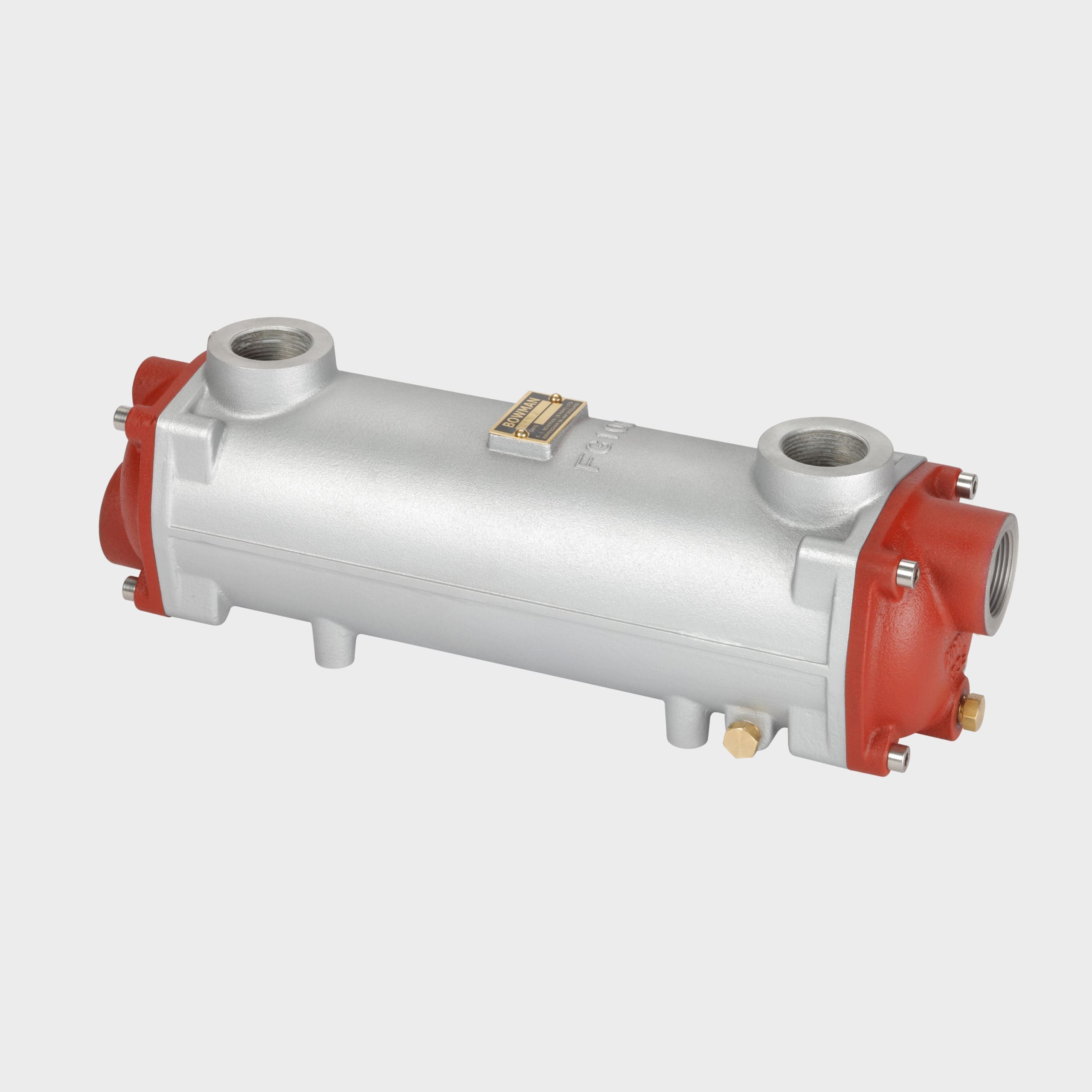
Bowman charge air coolers and exhaust gas heat exchangers are playing a key part of a co-generation system that has halved electricity costs for a remote Canadian community. Located in the Northwest Territories of Canada, Fort Providence is a small hamlet of about 800 people, approximately 2,000 km north of the Canada-USA border. Winters are very cold, with temperatures falling to -40°C, making power and heat highly valued and expensive commodities. In 24 of 32 communities in the Northwest Territories, electricity is produced using diesel generators. The commercial rate per kilowatt hour ranges between $0.51 and $0.61 CDN, which is four or five times the utility rates in southern Canada. Diesel has to be trucked or sea-lifted long distances from the south, hence the high cost of power.
Continue Reading »