Air to water heat exchangers that help improve engine efficiency and reduce emissions for marine and land-based stationary engines.
Charge air coolers reduce the temperature of engine combustion air after it has passed through the turbocharger, improving the volumetric efficiency by providing a denser intake charge to the engine. Bowman manufacture a comprehensive range of charge air coolers designed for use with both marine and land-based stationary engines rated up to 850 kW.
For land-based installations, standard units are supplied with cast iron covers, or where sea water is used for cooling, marine specification end covers are fitted.
High Efficiency
Bowman charge air coolers provide extremely high levels of heat transfer due to the innovative design of the tube stack and baffle plates.
Easy Maintenance
The fully floating tube stacks can be easily removed from the body of the intercooler allowing for simple maintenance and cleaning.
Specification
Charge Air Coolers – Typical Performance and Dimensions
The following information offers a general guide to the performance and dimensions of our standard range of charge air coolers. For more detailed information on additional configurations and specific applications, please download the product brochure. Computer aided selection software (CAS) can be used to accurately select the correct heat exchanger specifically for your application.
Note – Marine intercoolers use materials suitable for sea water to be used as the cooling medium. The drawing below is a marine charge air cooler and is fitted with Naval brass end covers.
Please contact us or your nearest stockist with the following information to receive a CAS selection:
Charge air mass flow rate
Charge air pressure and maximum allowable pressure drop
Charge air inlet and desired outlet temperature
Cooling water source, temperature and flow rate
The image above is representative of the range of Charge Air Coolers from EC120 to RK250.
Note – Hose connections are not available on PK and RK charge air cooler models. See the brochure for details of the flanged connections.
Type
Engine Power (kW)
Charge Air Flow (kg/min)
Heat Rejection (kW)
Pressure Drop (kPa)
Dim. A (mm)
Dim. B (mm)
Dim. C (mm)
EC120
50
2.5
5.3
2.1
346
212
94
FC100
90
4.3
9.1
3.0
358
190
112
FG100
120
9.8
20.8
5.3
472
272
132
GL140
175
15.4
32.9
7.3
502
272
170
GK190
280
20.3
46.8
5.3
674
370
206
JK190
365
30.1
70.3
7.4
704
350
240
PK250
570
40.3
95.0
3.9
852
446
286
RK250
850
60.0
146.6
7.9
1012
432
350
Downloads
Charge Air Coolers
Technical sales brochure includes product information, ratings charts, drawings and dimensions for the standard product range.
Installation Manual for Charge Air Coolers
Download our installation manual for the charge air coolers here.
If you can’t stand the heat – get a Bowman heat exchanger! How Bowman heat exchangers have solved a major cooling headache for a Portuguese river cruising company.
A heat exchanger is a device for transferring heat energy from a liquid or gas, to another liquid or gas without the two ever coming into contact with each other. A typical shell and tube heat exchanger will contain a tube bundle inside an outer shell, or body. Cold water flows through these tubes, whilst hot water, or gas flows around the outside of the tubes, enabling the heat from the hot water or gas to be transferred to the colder water inside the tubes.
A good example of how the process works are swimming pools, where most are heated via a boiler, using Gas, LPG or Biomass as the energy source. In theory, the most efficient way to heat the pool would be to circulate the pool water directly through the boiler. But were this to happen, the chemicals used in the pool water to keep it safe for use, would quickly corrode and damage vital parts inside the boiler, leading to premature failure and a costly replacement.
However, by using a heat exchanger to act as an ‘interface’ between the boiler water circuit and the pool water circuit, the boiler is protected from damage and the pool water is quickly heated up to the required temperature; the pool water passing through the central ‘tube core’, whilst the hot boiler water circulates around the outside of the tubes, transferring heat energy to the pool water.
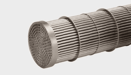
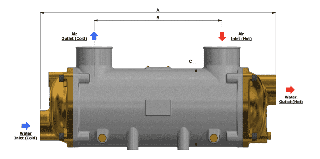
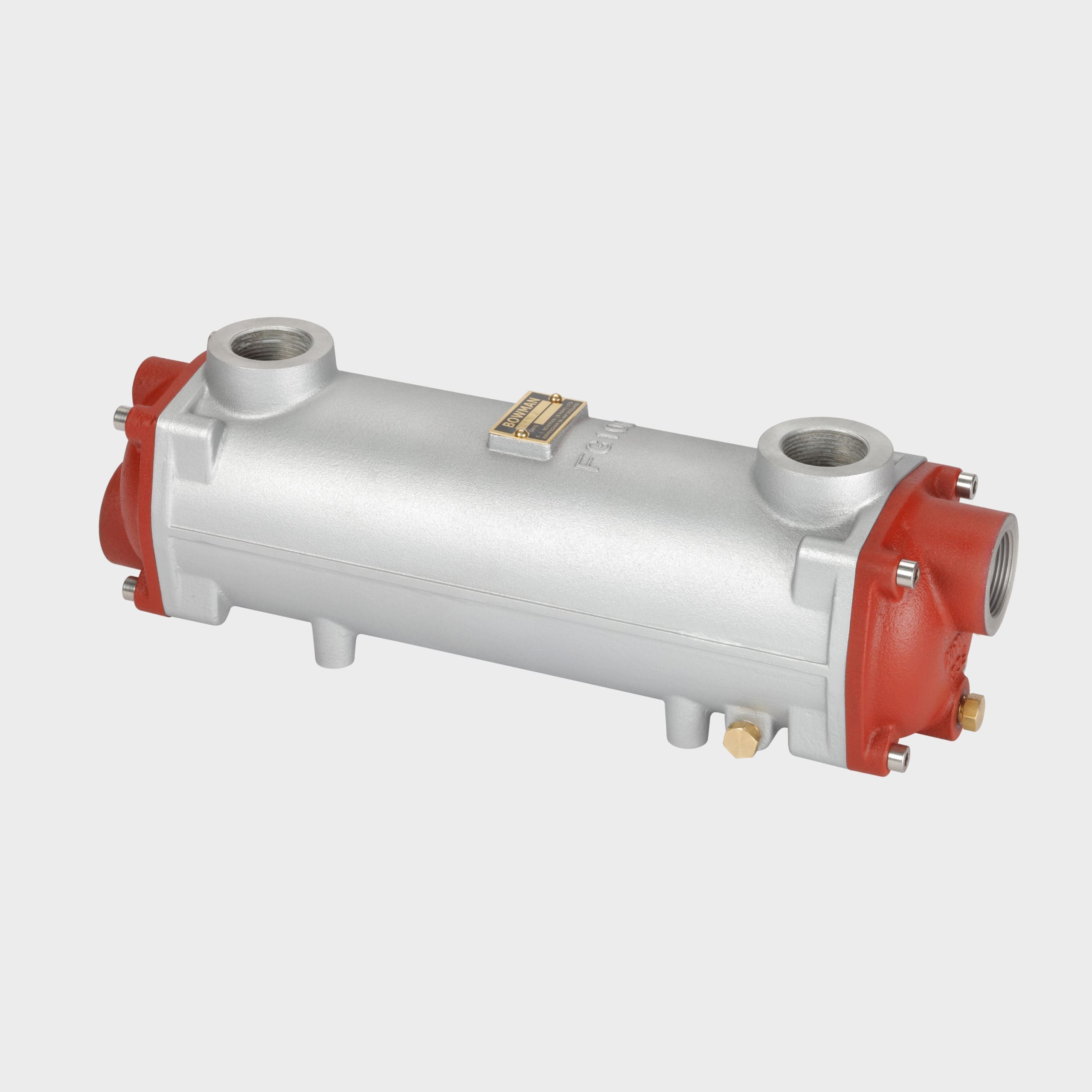
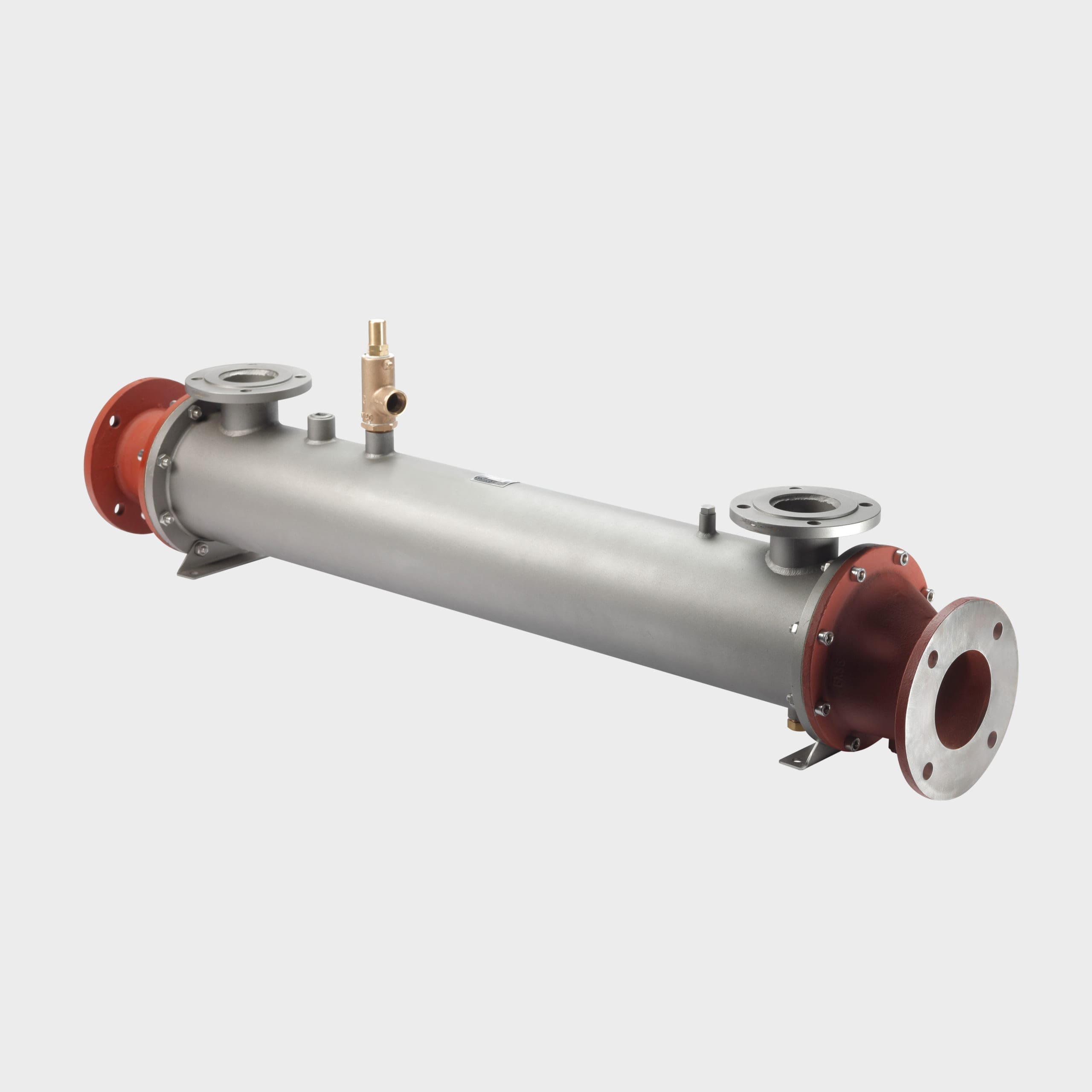
In a shell and tube heat exchanger, coolant usually flows through the central ‘tube core’ to cool hot oil, water or air, which passes over and around the tubes. The direction in which the two fluids travel through the heat exchanger can be either ‘parallel flow’ or ‘counterflow’.
Parallel flow is where the fluid to be cooled, flows through the heat exchanger in the same direction as the cooling medium. Whilst this arrangement will provide cooling, it has limitations and can also create thermal stress within the heat exchanger, as one half of the unit will be appreciably warmer than the other.
In counterflow cooling, the incoming cooling medium absorbs more heat as the ‘hot’ fluid travels in the opposite direction. The cooling medium heats up as it travels through the heat exchanger, but as colder water enters the heat exchanger it absorbs more heat, reducing the temperature much lower than could be achieved with parallel flow.
The mean temperature difference between the cooling medium and the fluid being cooled is also more uniform along the length of the heat exchanger, reducing thermal stress.
Depending on flow rate and temperature, the heat transfer performance could be up to 15% more efficient with counterflow, possibly enabling a smaller heat exchanger to be used, saving space and money!
During the course of its operating life, a shell and tube heat exchanger will need cleaning many times. Both fresh water and sea water cooling media today contain high levels of minerals and pollutants, which can build up over time, restricting the water flow through the tube core, resulting in a reduced flow rate and significantly lower heat transfer efficiency.
The good news is that Bowman shell and tube heat exchangers are much easier to clean than many other types and the following information is intended as a basic guide:
Removing the end covers gives access to the tube core, which can be removed from the body (or shell).
The tube plates and external tubes can then be washed using a handheld hose or lance. A steam cleaner can also be used, if available.
Small diameter rods or tube brushes can be used to clean through each tube to remove any stubborn deposits.
Detergents or chemicals can be used, if tube fouling is severe. Allow plenty of time for the cleaning media to work before hosing down with plenty of water. NOTE: it is important to check any cleaners being used are compatible with the tube material.
Thoroughly flush the tube core with clean water to remove all traces of cleaning chemicals/detergents and if necessary, neutralise the cleaning fluid.
Reassemble the tube core into the body, refit the end covers in their original orientation and tighten to the recommended torque figures – NOTE: always use new ‘O’ seals after cleaning to ensure a watertight joint.